You need to understand what principles microservice architecture has been built
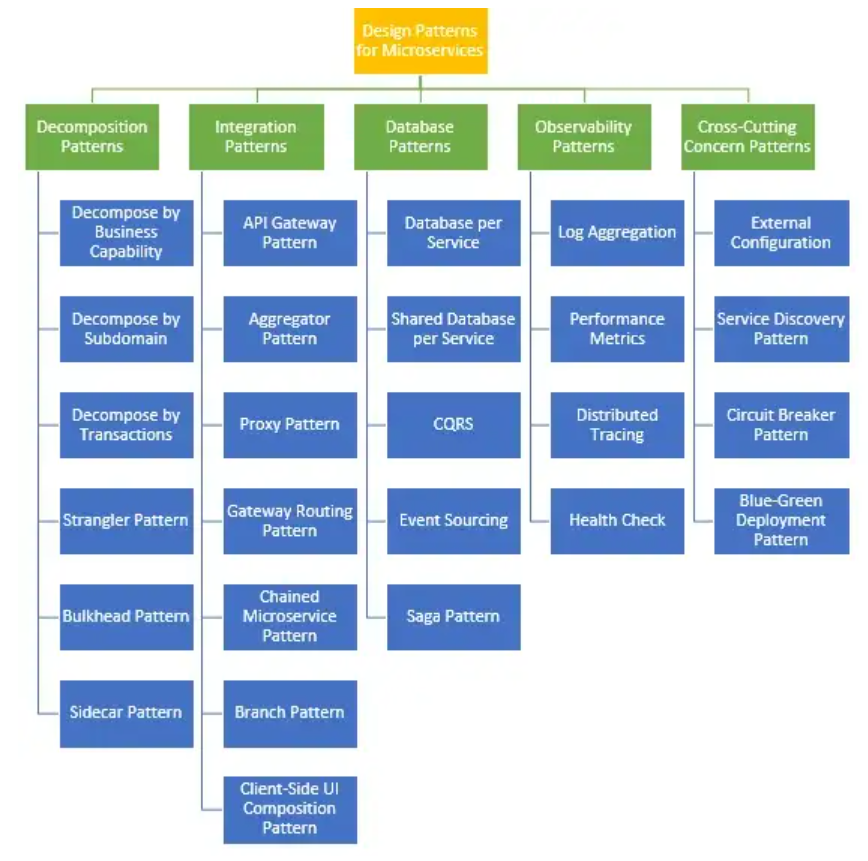
Add hearing to the above principles, brings several challenges and issues while bring your solution or system to live. Those problems are common for many solutions. Those can overcome with using correct and matching design patterns. There are design patterns for microservices and those can divide into five Patterns. Each many contains many patterns. Below diagram shows the those.
| Decompose by Business Capability | Microservices is all about making services loosely coupled, applying the single responsibility principle. It decomposes by business capability. Define services corresponding to business capabilities. A business capability is a concept from business architecture modeling [2]. It is something that a business does in order to generate value. A business capability often corresponds to a business object, e.g.
|
| Decompose by Subdomain | Decomposing an application using business capabilities might be a good start, but you will come across so-called “God Classes” which will not be easy to decompose. These classes will be common among multiple services. Define services corresponding to Domain-Driven Design (DDD) subdomains. DDD refers to the application’s problem space — the business — as the domain. A domain is consists of multiple subdomains. Each subdomain corresponds to a different part of the business. Subdomains can be classified as follows:
The subdomains of an Order management include:
|
| Decompose by Transactions / Two-phase commit (2pc) pattern | You can decompose services over the transactions. Then there will be multiple transactions in the system. One of the important participants in a distributed transaction is the transaction coordinator [3]. The distributed transaction consists of two steps:
The problem with 2PC is that it is quite slow compared to the time for operation of a single microservice. Coordinating the transaction between microservices, even if they are on the same network, can really slow the system down, so this approach isn’t usually used in a high load scenario. |
| Strangler Pattern | Above three, design patterns that you go through were decomposing applications for Greenfield, but 80% of the work you do is with brownfield applications, which are big, monolithic applications (legacy codebase). The Strangler pattern comes to the rescue or solution. This creates two separate applications that live side by side in the same URI space. Over time, the newly refactored application “strangles” or replaces the original application until finally, you can shut off the monolithic application. The Strangler Application steps are transform, coexist, and eliminate [4]:
|
| Bulkhead Pattern | Isolate elements of an application into pools so that if one fails, the others will continue to function. This pattern is named Bulkhead because it resembles the sectioned partitions of a ship’s hull. Partition service instances into different groups, based on consumer load and availability requirements. This design helps to isolate failures, and allows you to sustain service functionality for some consumers, even during a failure. |
| Sidecar Pattern | Deploy components of an application into a separate processor container to provide isolation and encapsulation. This pattern can also enable applications to be composed of heterogeneous components and technologies. This pattern is named Sidecar because it resembles a sidecar attached to a motorcycle. In the pattern, the sidecar is attached to a parent application and provides supporting features for the application. The sidecar also shares the same lifecycle as the parent application, is created and retired alongside the parent. The sidecar pattern is sometimes referred to as the sidekick pattern and is the last decomposition pattern that we show in the post. |
| API Gateway Pattern | When an application is broken down to smaller microservices, there are a few concerns that need to be addressed
An API Gateway helps to address many concerns raised by the microservice implementation, not limited to the ones above.
|
| Aggregator Pattern | When breaking the business functionality into several smaller logical pieces of code, it becomes necessary to think about how to collaborate the data returned by each service. This responsibility cannot be left with the consumer. The Aggregator pattern helps to address this. It talks about how we can aggregate the data from different services and then send the final response to the consumer. This can be done in two ways [6]:
It is recommended if any business logic is to be applied, then choose a composite microservice. Otherwise, the API Gateway is the established solution. |
| Proxy Pattern | API gateway we just expose Microservices over API gateway. I allow to get API features such as security and categorizing APIs in GW. In this example, the API gateway has three API modules:
|
| Gateway Routing Pattern | The API gateway is responsible for request routing. An API gateway implements some API operations by routing requests to the corresponding service. When it receives a request, the API gateway consults a routing map that specifies which service to route the request to. A routing map might, for example, map an HTTP method and path to the HTTP URL of service. This function is identical to the reverse proxying features provided by web servers such as NGINX. |
| Chained Microservice Pattern | There will be multiple dependencies of for single services or microservice eg: Sale microservice has dependency products microservice and order microservice. Chained microservice design pattern will help you to provide the consolidated outcome to your request. The request received by a microservice-1, which is then communicating with microservice-2 and it may be communicating with microservice-3. All these services are synchronous calls. |
| Branch Pattern | A microservice may need to get the data from multiple sources including other microservices. Branch microservice pattern is a mix of Aggregator & Chain design patterns and allows simultaneous request/response processing from two or more microservices. The invoked microservice can be chains of microservices. Brach pattern can also be used to invoke different chains of microservices, or a single chain, based your business needs. |
| Client-Side UI Composition Pattern | When services are developed by decomposing business capabilities/subdomains, the services responsible for user experience have to pull data from several microservices. In the monolithic world, there used to be only one call from the UI to a backend service to retrieve all data and refresh/submit the UI page. However, now it won’t be the same. With microservices, the UI has to be designed as a skeleton with multiple sections/regions of the screen/page. Each section will make a call to an individual backend microservice to pull the data. Frameworks like AngularJS and ReactJS help to do that easily. These screens are known as Single Page Applications (SPA). Each team develops a client-side UI component, such an AngularJS directive, that implements the region of the page/screen for their service. A UI team is responsible for implementing the page skeletons that build pages/screens by composing multiple, service-specific UI components. |
Defining the database architecture for microservices we need to consider below points.
| Database per Service | To solve the above concerns, one database per microservice must be designed; it must be private to that service only. It should be accessed by the microservice API only. It cannot be accessed by other services directly. For example, for relational databases, we can use private-tables-per-service, schema-per-service, or database-server-per-service. |
| Shared Database per Service | We have talked about one database per service being ideal for microservices. It is anti-pattern for microservices. But if the application is a monolith and trying to break into microservices, denormalization is not that easy. Later phase we can move to DB per services pattern, Till that we make follow this.A shared database per service is not ideal, but that is the working solution for the above scenario. Most people consider this an anti-pattern for microservices, but for brownfield applications, this is a good start to break the application into smaller logical pieces. This should not be applied for greenfield applications. |
| Command Query Responsibility Segregation (CQRS) | Once we implement database-per-service, there is a requirement to query, which requires joint data from multiple services. it’s not possible. CQRS suggests splitting the application into two parts — the command side and the query side.
The event sourcing pattern is generally used along with it to create events for any data change. Materialized views are kept updated by subscribing to the stream of events. |
| Event Sourcing | Most applications work with data, and the typical approach is for the application to maintain the current state. For example, in the traditional create, read, update, and delete (CRUD) model a typical data process is to read data from the store. It contains limitations of locking the data with often using transactions. The Event Sourcing pattern [8] defines an approach to handling operations on data that’s driven by a sequence of events, each of which is recorded in an append-only store. Application code sends a series of events that imperatively describe each action that has occurred on the data to the event store, where they’re persisted. Each event represents a set of changes to the data (such as AddedItemToOrder). The events are persisted in an event store that acts as the system of record. Typical uses of the events published by the event store are to maintain materialized views of entities as actions in the application change them, and for integration with external systems. For example, a system can maintain a materialized view of all customer orders that are used to populate parts of the UI. As the application adds new orders, adds or removes items on the order, and adds shipping information, the events that describe these changes can be handled and used to update the materialized view. The figure shows an overview of the pattern. |
| Saga Pattern | When each service has its own database and a business transaction spans multiple services, how do we ensure data consistency across services. Each request has a compensating request that is executed when the request fails. It can be implemented in two ways:
|
| Log Aggregation | Consider a use case where an application consists of multiple services. Requests often span multiple service instances. Each service instance generates a log file in a standardized format. We need a centralized logging service that aggregates logs from each service instance. Users can search and analyze the logs. They can configure alerts that are triggered when certain messages appear in the logs. For example, PCF does have Log aggregator, which collects logs from each component (router, controller, diego, etc…) of the PCF platform along with applications. AWS Cloud Watch also does the same. |
| Performance Metrics | When the service portfolio increases due to a microservice architecture, it becomes critical to keep a watch on the transactions so that patterns can be monitored and alerts sent when an issue happens. A metrics service is required to gather statistics about individual operations. It should aggregate the metrics of an application service, which provides reporting and alerting. There are two models for aggregating metrics:
|
| Distributed Tracing | In a microservice architecture, requests often span multiple services. Each service handles a request by performing one or more operations across multiple services. While in troubleshoot it is worth to have trace ID, we trace a request end-to-end. The solution is to introduce a transaction ID. Follow approach can be used;
|
| Health Check | When microservice architecture has been implemented, there is a chance that a service might be up but not able to handle transactions. Each service needs to have an endpoint which can be used to check the health of the application, such as /health. This API should o check the status of the host, the connection to other services/infrastructure, and any specific logic. |
| External Configuration | A service typically calls other services and databases as well. For each environment like dev, QA, UAT, prod, the endpoint URL or some configuration properties might be different. A change in any of those properties might require a re-build and re-deploy of the service. To avoid code modification configuration can be used. Externalize all the configuration, including endpoint URLs and credentials. The application should load them either at startup or on the fly. These can be accessed by the application on startup or can be refreshed without a server restart. |
| Service Discovery Pattern | When microservices come into the picture, we need to address a few issues in terms of calling services. With container technology, IP addresses are dynamically allocated to the service instances. Every time the address changes, a consumer service can break and need manual changes. Each service URL has to be remembered by the consumer and become tightly coupled. A service registry needs to be created which will keep the metadata of each producer service and specification for each. A service instance should register to the registry when starting and should de-register when shutting down. There are two types of service discovery:
|
| Circuit Breaker Pattern | A service generally calls other services to retrieve data, and there is the chance that the downstream service may be down. There are two problems with this: first, the request will keep going to the down service, exhausting network resources, and slowing performance. Second, the user experience will be bad and unpredictable. The consumer should invoke a remote service via a proxy that behaves in a similar fashion to an electrical circuit breaker. When the number of consecutive failures crosses a threshold, the circuit breaker trips, and for the duration of a timeout period, all attempts to invoke the remote service will fail immediately. After the timeout expires the circuit breaker allows a limited number of test requests to pass through. If those requests succeed, the circuit breaker resumes normal operation. Otherwise, if there is a failure, the timeout period begins again. This pattern is suited to, prevent an application from trying to invoke a remote service or access a shared resource if this operation is highly likely to fail. |
| Blue-Green Deployment Pattern | With microservice architecture, one application can have many microservices. If we stop all the services then deploy an enhanced version, the downtime will be huge and can impact the business. Also, the rollback will be a nightmare. Blue-Green Deployment Pattern avoid this. The blue-green deployment strategy can be implemented to reduce or remove downtime. It achieves this by running two identical production environments, Blue and Green. Let’s assume Green is the existing live instance and Blue is the new version of the application. At any time, only one of the environments is live, with the live environment serving all production traffic. All cloud platforms provide options for implementing a blue-green deployment. |
| References [1] “Microservice Architecture: Aligning Principles, Practices, and Culture” Book by Irakli Nadareishvili, Matt McLarty, and Michael Amundsen [2] https://microservices.io/patterns/decomposition/decompose-by-business-capability.html [3] https://www.baeldung.com/transactions-across-microservices [4] https://developer.ibm.com/articles/cl-strangler-application-pattern-microservices-apps-trs/ [5] https://docs.microsoft.com/en-us/azure/architecture/patterns/bulkhead [6] https://dzone.com/articles/design-patterns-for-microservices [7] https://docs.microsoft.com/en-us/azure/architecture/patterns/cqrs#event-sourcing-and-cqrs [8] https://docs.microsoft.com/en-us/azure/architecture/patterns/event-sourcing [9] https://www.dineshonjava.com/microservices-with-spring-boot/ [10] https://docs.microsoft.com/en-us/azure/architecture/patterns/circuit-breaker |